Rc-40.doc
RC-40 Temperature and humidity Data LoggerOperation Instruction
1. Product overview
RC-40 Temperature and humidity Data Logger , Segment LCD display, one channel temperature and one channel humidity as its standard configuration, it could be expanded to four channels, temperature or humidity mode optional, internal rechargeable lithium battery, RS-485 network can be set up, support the U disk copy and USB data transmission. It has the advantages of wide temperature range, high accuracy, big record capacity, etc. The segment LCD could display the system clock, the current work status, record capacity and recorded data; it has the output of buzzer and alarm relay. Its data-processing software has the functions of real-time transmission, historical data uploading, data saving and The product is widely used in industries of foodstuff, medicine, cold-chain transportation and other industries accordant with HACCP system certification. It could also be used in laboratory where needs temperature and humidity supervision. 2. Product Features:
Monitor and record temperature and humidity data Temperature record cycle could be flexibly adjusted Large record capacity. If record every 15 minutes, it could record for more than ten Big LCD screen can simultaneously display system clock, current work status, record capacity and recorded data. The upper/lower temperature alarm temperature could be separately set. It will alarm when the temperature exceeds the upper or lower limit. It has USB /U disk interface for convenient data copy and save. Form a Local Area Network by RS-485 interface to monitor several data loggers' It is matched with our RC-40 data processing software which could real-time monitor, upload, print and manage the data It has two alarm output: Buzzer and alarm relay with rechargeable standby batteries, when the power is cut off, it could keep running for ninety days after fully charged. 3. Specification:
Product Size: Length: 133mm Width: 128mm Depth: 34mm 4. Technical parameters:
Power Supply: 12V AC / DC 24V AC / DC, It could connect with 100 264VAC, 50/60HZ by external power adaptor ◇Temperature Measuring Range: -50.0℃~120.0℃ ◇ Temperature accuracy: ± 0.5 ℃ for (-30 ℃ +20℃) ; ± 1 ℃ for-30℃<temperature<-40℃,or 20℃<temperature<70℃; ± 2 ℃ for others; (If sensor wire is longer than 50 M, accuracy deviation 1%); ◇ Humidity measuring range: 0~99%RH ◇ Display Resolution: 0.1 ◇ Humidity accuracy: (@25℃):+5%RH (typical); (@10~40℃): 0~59%RH: + 6%RH (max) 60~95%RH: + 8%RH (max) ◇ Temperature sensor type: NTC ◇ Humidity sensor type: Honeywell ◇ Record Cycle: 1 minute to 24 hours continuously set ◇ Record Capacity: Each channel 30,000 points (MAX) ◇ Applicable Environment: Temperature -20 ℃ 50 ℃; Humidity 0% 95% ◇ Alarming output:Buzzer and alarm relay ◇ Communication interface:USB/U-disk interface, RS-485 ◇ Sensor input interface:Dual channel input, for temperature or for humidity optional; the sensor interface could be expanded to four channel temperature sensors or two channel humidity sensors and two channel temperature sensors. ◇ Standby battery: 3.7V 2200mAH lithium battery

5.Panel interface:
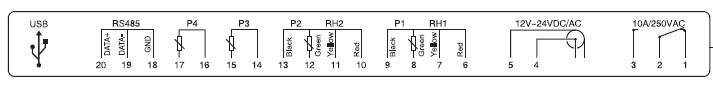
6. Wiring Terminal Description
RC-40 Wiring Terminal Diagram sees Figure 6.1
Figure 6.1 RC-40 Wiring Terminal Diagram
RC-40 Wiring Terminal Description:
1,2 NO 2,3 NC 10A/250VAC
4(Positive), 5(negative) 12V AC / DC 24V AC / DC
When a switch power adapter is used, it could connect to a round socket.
Humidity Sensor Input 1:
6(red), 7(yellow), 8(green), 9(black)
Temperature Sensor Input 1:
Humidity Sensor Input 2:
10(red), 11 (yellow), 12(green), 13(black)
Temperature Sensor Input 2:
Temperature Sensor Input 2:
Temperature Sensor Input 2:
Data transmission interface:
RS485 interface: 18 (GND) 19 (DATA-) 20 (DATA+)
U-disk interface: USB
Note: (1) When connect it to PC by RS-485 interface; RS-232/RS-485 converter is needed.
(2) When connect it to PC by U disk, USB cable is needed.
(3) When copy data by U disk, It needs to connect external power for more than five
seconds, and then insert the U disk. The file system format in U disk should be
FAT32 or FAT. Before copy, the saved file RC-40.TXT in U disk needs to be
renamed or resaved; otherwise, it will be overwritten during copying.
(4) Before revise the sensor type, it needs to copy the saved data in the data logger,
and clear the data.
(5) If select GSM alarm module, cut off the external power before insert SIM card,
wait until the GSM signal indicator is off, then insert SIM card. After confirm SIM
card is well inserted, and then reconnect the external power.
7. Parameter list:
Parameter
Function
Set range
Setting of Month
MODE F05 Setting of Minute
MODE F06 Baud rate setting
MODE F07 Address setting
Record interval(Hour)
MODE F09 Record interval(Minute)
MODE F10 Sensor 1 setting
Sensor 2 setting
MODE F12 Sensor 3 setting
Sensor 4 setting
MODE F14 Sensor 1 upper limit
Temp: (-48.9 120.0℃)
Humidity:(1.1 100%)
Sensor 1 lower limit
Temp: (-50.0 118.9℃)
Humidity:(0.0 98.9%)
Sensor 2 upper limit
Temp: (-48.9 120.0℃)
Humidity: (1.1 100%)
Sensor 2 lower limit
Temp: (-50.0 118.9℃)
Humidity: (0.0~98.9%)
Sensor 3 upper limit
Temp: (-48.9 120.0℃)
MODE F19 Sensor 3 lower limit
Temp: (-50.0 118.9℃)
MODE F20 Sensor 4 upper limit
Temp: (-48.9 120.0℃)
Sensor 4 lower limit
Temp: (-50.0 118.9℃)
MODE F22 Sensor 1 calibration
Temp: (-10.0 10.0℃)
Humidity(-10.0 10.0)
Sensor 2 calibration
Temp: (-10.0 10.0℃)
Humidity: (-10.0 10.0)
MODE F24 Sensor 3 calibration
Temp.: (-10.0 10.0℃)
MODE F25 Sensor 4 calibration
Temp.: (-10.0 10.0℃)
Clear saved data
8. Operation Instruction:
RC-40 mainly has four working state:
1. Normal working state
2. System setting state
3. Record query state
4. Data clear state
Note: When RC-40 is electrified, it enters normal working state.
8.1 The interface description of normal working state:
RC-40 normal status, "Act" represents the normal state interface.
External power indication
Figure 8.1 Scheme of power supply interface
When external power is cut off, it display battery work state, and during this state, buzzer,
relay, U disk, RS485 close. See Figure 8.2
Battery indication
Figure 8.2 Scheme of battery powered interface
Under the work state of ACT
When the external power is connected, and insert U disk, hold and press key SET for about
five to ten minutes to copy data, do not release the key until the icon of U disk flashes. After
finishing copy, when the icon of U disk stops flashing, the U disk could exit. If GSM module
has been selected, it needs to wait for 60 seconds after connect external power supply, and
then long press SET key to copy data. If there is read-write lock in U disk, please open the
read-write lock. If there is no U disk icon flashing over 15 seconds, please check whether file
format in U disk is in FAT32 or FAT in computer, and check whether the files in U disk could
be normally read or written, see Figure 8.3
U disk copy indication
Figure 8.3 Scheme of U disk copy interface
The file name of U disk copy is RC-40.TXT, it could be opened by the notepad, WordPad or
Office Word in Windows, an example, please see Figure 8.4
Figure 8.4 Example of U disk copy file
The representation of symbols shown above is as below:
1. "NO." represents record sequence number
2. "DATE" represents record date
3. "TIME" represents record time
4. "P1" represents this channel is temperature sensor.
5. "RH2" represents this channel is humidity sensor
6. "OFF" represents this channel has been closed, there is no sensor.
7. "--.-" represents sensor in short-circuit or in break circuit failure
8. "POWER" represents the method of power supply
9. "EXT-PWR" represents the external power supply
10. "BAT" represents the cutoff of external power and it is powered by internal battery.
Connect the data logger with computer by USB cable, and then the recorded data could be
uploaded to PC. See Figure 8.5
Figure 8.5 Scheme of USB data uploading interface
8.2 System setting interface
Under the state of ACT:
to enter the parameter setting state MODE, then press ▲ or ▼ to select the
parameter menu, the menu is F01、F02……F35.After a menu is selected, press
the corresponding value, and this value will flash. Press ▲ or ▼ to modify this parameter,
,the cursor will shift in circulation,press SET to save the parameter. Parameter
setting please refer to "parameter list".
8.3 Record query interface
Under the state of ACT:
Press▼ to enter the state of historical record data query "Log",press▼ to query data
forward,press ▲ to query date backward,long press ▲ or ▼ to quicken the query. During
to check the record time. If channel 3 and channel 4 are also enabled, the
record data in Channel 3 and Channel 4 could also be checked. In the query mode, if no key
operation within four seconds, the interface will auto switch and display date and time
separately. If Channel 3 and Channel 4 are enabled, display the data from Sensor 3 and
Sensor 4. If no key operation within 15 seconds, it will return to normal work state
automatically, or press SET to return to normal work state. See 8.6
Date of record data
Figure 8.6 Scheme of record data query interface
8.4 Record data clearing:
Under the work state ACT, press
to enter parameter setting, and press▲ or ▼ to select,
see Figure 8.7. Press
to enter the setting,press
to select the digit of password,press
▲ or ▼ to modify the password from "000" to "123",press SET key to exit,and in LCD screen,
it displays "CLr",it means that data clearing succeeds. If display "Err",means data clearing
fails, please press
again to reset the password.
Figure 8.7 Scheme of record data clearing menu
8.5 Alarm work state interface
When it is powered by external power, if the measured temperature or humidity exceeds the
upper or lower limit, or when the sensors are in short circuit or in break circuit, the buzzer
will beep and the reply pick up, the alarm interface is as follows. When alarming, press any
key to cancel buzzer alarm. While if there is an alarm in other sensor, the buzzer alarm will
Sensor 1 temperature upper limit
Buzzer alarm indication
Sensor 2 short/break circuit alarm
Figure 8.8 Scheme of alarm interface
Note: If external power supply is cut off, and it is only powered by battery, when there is an
alarm, thee buzzer will not beep and the alarm reply will be canceled.
9. Communication Means Selection:
Selection mode of data transmission:
1. For single RC-40, its data could be transmitted to PC by U disk or by USB interface, and
then connect U disk to the computer for data analysis. Please see Figure 9.1 and 9.2.
Figure 9.1 Scheme of data transmission by USB
Figure 9.2 Scheme of data transmission by U disk
2. Multiple RC-40 form LAN by RS-485 interface:
Multiple RC-40 devices can form a Local Area Network by connecting to the RS-232/RS-485
converter at the computer terminal via RS-485 bus. It could assign different addresses for
each RC-40 in the LAN by setting parameter entry "MODE F07" with the address range from
1 to 80. See Figure 9.3
All data of the device in LAN could be monitored, uploaded by the computer software and be
saved and printed in graphic or table forms.
Figure 9.3 Multiple devices RC-40 form LAN by RS-485 interface
Note: Baud rate could be automatically set by the computer software (Default baud rate
10. Device Standard Accessories
■ RC-40 Temperature and Humidity Data Logger ■ Temperature Sensor (length: 5M) ■ Humidity Sensor (length: 5M) ■ One Computer Installation Software CD ■ One Operation Instruction ■ One Power Adaptor
11. Optional Accessories
▽ RS232/RS485 Converter
▽ Humidity Sensor
▽ Temperature Sensor
Source: http://ideaaircon.com.ua/sites/default/files/downloadables-documents/rukovodstvo/ru//termometr_rd-40_recorder-manual.pdf
Topical steroids.indd
Topical steroids for children with asthma Topical steroids for children with asthma Professor, overlæge, dr. med. Dansk BørneAstma Center Gentofte Børneafdeling Steroids are the most effective preventive medication for the treatment of asthma in children. The inhalation of steroids helps asthmatic children to lead normal lives and has no relevant side effects in recommended dose. Therefore, pediatricians recommend that children with regular symptoms of asthma should be treated with inhaled steroids.
veranstaltungen.handelsblatt.com
Statista-Dossier Arzneimittel - Statista-Dossier © Statista GmbH, Hamburg Arzneimittel - Statista-Dossier Überblick Weltweiter Pharmamarkt - Umsatz 2003-2012 Arzneimittelausgaben - Pro-Kopf-Ausgaben ausgewählter Länder 2013 Pharmaunternehmen - Umsatzstärkste Pharmakonzerne 2013 Pharma-Gesamtmarkt in Deutschland - Umsatzentwicklung bis 2013