Trimble dini digital level user guide
Trimble® DiNi® Digital LevelVersion 2.0Part Number 57345002December 2007 Corporate Office
Trimble Navigation Limited
645 North Mary Avenue
PO Box 3642
Sunnyvale, CA 94085
Geomatics and Engineering Division
5475 Kellenburger Road
Dayton, Ohio 45424-1099
USA
800-538-7800 (toll free in USA)
www.trimble.com
Copyright and Trademarks
2006-2007, Trimble Navigation Limited. All rights
reserved. Trimble, the Globe & Triangle logo and DiNi are
trademarks of Trimble Navigation Limited, registered in the United States Patent and Trademark Office and in other countries.
All other trademarks are the property of their respective
owners.
This product is covered by the following patents: DE
3739664; DE 4419524; US 5572009 and US 5802206
Release Notice
This is the December 2007 release of the Trimble DiNi
User Guide, part number 57345002, version 2.0
Product Warranty Information
For applicable product warranty information, please
refer to the Warranty Card included with this Trimble
product, or consult your Trimble dealer.
Notices
Europe
This product has been tested and found to
comply with the requirements for a Class B
device pursuant to European Council Directive
89/336/EEC on EMC, thereby satisfying the requirements
for CE Marking and sale within the European Economic
Area (EEA). These requirements are designed to provide
reasonable protection against harmful interference
when the equipment is operated in a residential or
commercial environment.
Australia and New Zealand
This product conforms with the regulatory
requirements of the Australian Communications
Authority (ACA) EMC framework, thus satisfying
the requirements for C-Tick Marking and sale within
Australia and New Zealand.
Taiwan – Battery Recycling Requirements
The product contains a removable Lithium-ion
battery. Taiwanese regulations require that waste
batteries are recycled.
Notice to Our European Union Customers
For product recycling instructions and more
information, please go .trimble.com/ev.shtml.
Recycling in Europe: To recycle Trimble WEEE
(Waste Electrical and Electronic Equipment,
products that run on electrical power.), Call
+31 497 53 24 30, and ask for the "WEEE
Associate". Or, mail a request for recycling
Trimble Europe BV
c/o Menlo Worldwide Logistics
Meerheide 45
5521 DZ Eersel, NL
Carefully read the manual before the first use. Be sure to comply with the safety information. Instruments and original accessories from Trimble must only be used for the intended purpose. C WARNING – Operate the instrument only in the compliance with the operating conditions
- Do not point the telescope directly at the sun.
- Do not use the instrument and accessories in rooms with danger of explosion.
- When you work with staves in the vicinity of electric plants (e.g. electric railways, aerial lines, transmitting stations, etc.) your life is acutely endangered. This risk exists independent of thematerial (e.g. aluminium or wood). In such cases it is necessary to inform the competentand authorised safety authorities and observe their instructions.
- Protect operator and instrument sufficiently at the site of measurement (e.g. construction site, roads, etc.). Observe any relevant national regulations and the Road Traffic Act.
- Do not carry out surveying work in a thunderstorm to avoid being struck by a lightning.
Battery Safety
C WARNING – Do not damage the rechargeable Lithium-ion battery. A damaged battery can
cause an explosion or fire, and can result in personal injury and/or property damage. Toprevent injury or damage: – Do not use or charge the battery if it appears to be damaged. Signs of damage include, but are not limited to, discoloration, warping, and leaking battery fluid. – Do not expose the battery to fire, high temperature, or direct sunlight.
– Do not immerse the battery in water. – Do not use or store the battery inside a vehicle during hot weather. – Do not drop or puncture the battery. – Do not open the battery or short-circuit its contacts.
C WARNING – Avoid contact with the rechargeable Lithium-ion battery if it appears to be leaking.
Battery fluid is corrosive, and contact with it can result in personal injury and/or propertydamage. To prevent injury or damage: – If the battery leaks, avoid contact with the battery fluid. – If battery fluid gets into your eyes, immediately rinse your eyes with clean water and seek medical attention. Do not rub your eyes! – If battery fluid gets onto your skin or clothing, immediately use clean water to wash off the battery fluid.
Trimble DiNi User Guide iii
Important Information C WARNING – Charge and use the rechargeable Lithium-ion battery only in strict accordance
with the instructions. Charging or using the battery in unauthorized equipment can cause an explosion or fire, and can result in personal injury and/or equipment damage. To prevent injury or damage: – Do not charge or use the battery if it appears to be damaged or leaking. – Charge the Lithium-ion battery only in a Trimble product that is specified to charge it.
Be sure to follow all instructions that are provided with the battery charger. – Discontinue charging a battery that gives off extreme heat or a burning odor. – Use the battery only in Trimble equipment that is specified to use it. – Use the battery only for its intended use and according to the instructions in the NOTICE FOR TRIMBLE'S EUROPEAN UNION CUSTOMERS Trimble is pleased to announce a new recycling program for our European Union customers. At Trimble, we recognize the importance of minimizing the environmental impacts of our products. We endeavor to meet your needs, not only when you purchase and use our products, but also when you are ready to dispose of them. That is why Trimble is actively pursuing, and will continue to pursue, the expanded use of environmentally friendly materials in all its products, and why we have established a convenient and environmentally friendly recycling program.
As Trimble makes additional recycling facilities available for your use, we will post their locations and contact information to our Recycling Instructions web page.
For product recycling instructions and more information, please go to Recycling in Europe:To recycle Trimble WEEE,Call +31 497 53 2430, and ask for the "WEEE Associate" Mail a request for recycling instructions to: Trimble Europe BVc/o Menlo Worldwide LogisticsMeerheide 455521 DZ Eersel, NL iv Trimble DiNi User Guide
Important Information CAUTION – Do not make any changes or repairs on the instrument and accessories. This must
be done only by a service team or by authorised technical staff.
- Do not initialise the data memory without making a back up of the stored data, as the initialisation will delete all stored data.
- Do tread tripod legs firmly into the ground to prevent sinking in and falling over of the instrument by wind pressure.
- Do mount the instrument to the tripod using the tripod screw immediately after you take the instrument from its case. - Do not leave the instrument placed loosely on the tripod head. After loosening the tripod screw, immediately store the instrument in its case.
- Do check your instrument at regular intervals in order to avoid faulty measurements, especially after it has been subjected to shock or heavy punishment.
- Do not use the instrument too long when it is raining. During breaks, cover the instrument with the protective hood. Wipe the instrument and case dry in the field and let it dry completelyindoors, with the case open.
- Do remove the batteries in case of unloading or a longer time without using the instrument.
- Do only recharge the batteries with the intended Trimble charger.
- Do properly dispose of the batteries and equipment taking into account the applicable national regulations. Prevent improper use of the disposed instrument by proper disposal - Do verify before every use of the instrument, that it is in perfect condition, particularly after longer transportation, fall or any other improper use. Systematicly check measurementsparticularly before and after extensive surveying projects will help to avoid erroneousmeasurements.
- Do not use destroyed plugs and cables for accessories with the instrument Trimble DiNi User Guide v
Important Information vi Trimble DiNi User Guide

Declaration of Conformity
Trimble DiNi
Trimble DiNi User Guide vii
Declaration of Conformity
viii Trimble DiNi User Guide
Trimble DiNi User Guide 1
2 Trimble DiNi User Guide
Trimble DiNi User Guide 3
4 Trimble DiNi User Guide
Trimble DiNi User Guide 5
6 Trimble DiNi User Guide
In this chapter:
Trimble DiNi User Guide 1
This manual describes how to set up and use the Trimble® DiNi® Digital Level.
Even if you have used other Digital Level products before, Trimble recommends that you spend some time reading this manual to learn about the special features of this product.
About the Trimble DiNi Digital Level
Although the principle of leveling has not changed, surveying today is no longer confined to the measurement of height differences. A demand now exists for complex measuring systems, which not only meet the increasing requirements for automatization, digital data processing and last but not least efficiency in everyday surveying, but which also set new standards in technology and operating convenience.
The DiNi fits excellently in the complete line of the measuring equipment from Trimble: Data interchange between all the instruments is ensured by a common data format and by the use of the USB Memory Stick.
Sources of related information include the following:
Trimble training courses – Consider a training course to help you use your Trimble Dini to its fullest potential. For more information, go to the Trimble website at
If you have a problem and cannot find the information you need in the product
documentation, contact your local dealer.
If you need to contact Trimble technical support:
Go to the Trimble website (
Click the Support button at the top of the screen. The Support A–Z list of
products appears.
Scroll to the bottom of the list.
Click the submit an inquiry link. A form appears.
Complete the form and then click Send.
Alternatively, you can send an e-mail to
2 Trimble DiNi User Guide
Your feedback about the supporting documentation helps us to improve it with each revision. E
To receive information regarding updates and new products please register on the Trimble web site.
Trimble DiNi User Guide 3
4 Trimble DiNi User Guide
Inspection, Care and Mainenance
In this chapter:
Trimble DiNi User Guide 5
2 Inspection, Care and Mainenance
Inspecting the Container
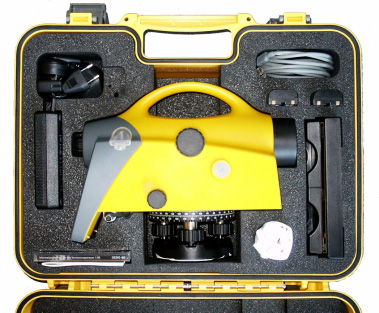
Inspect the shipping container. If the container arrives in poor condition, examine the equipment for visible damage. If damage is found, immediately notify the carrier and your Trimble sales representative. Keep the container and the packing material for the carrier to inspect.
When unpacking the instrument, check that all ordered items are received. Below is an example of where all items can be placed in the instrument case.
Note – Some of the items in the picture below are optional.
6 Trimble DiNi User Guide
Inspection, Care and Mainenance 2
Trimble DiNi Digital level
Battery (One battery standard)
Cable (DiNi to PC)
Battery charger**
Manual CD, Short form user guide, certificate
Power supply for battery charger**
Allen key for cross hair adjustment
Trimble DiNi User Guide 7
2 Inspection, Care and Mainenance
Care and Maintenance
C WARNING – Do not remove the instrument cover from the instrument. Trimble DiNi is designed
to withstand normal electromagnetic disturbance from the environment but it contains circuits that are sensitive to static electricity. If an unauthorized person opens the instrument cover, the function of the instrument is not guaranteed and the warranty invalidated.
The Trimble DiNi is designed and tested to withstand field conditions, but like all precision instruments, it requires care and maintenance. Take the following steps to get the best results from the instrument:
Do not subject the equipment to rough jolts or careless treatment.
Keep the lenses clean. Use only lens paper or other material that is designed for cleaning optical equipment.
When not in use, keep the instrument in the instrument case.
Carry the instrument by the handle.
When you need extremely precise measurements, make sure that the instrument has adapted to the surrounding temperature. Significant variations in instrument temperature can affect precision.
C CAUTION – Never use strong detergents such as benzine or thinners on the instrument or the
instrument case.
Be very careful when cleaning the instrument, especially when removing sand or dust from lenses and reflectors. Never use coarse or dirty cloth or hard paper. Trimble recommends that you use anti-static lens wad, a cotton wad, or a lens brush.
Getting rid of Moisture
If the instrument has been used in damp weather, take the instrument indoors and remove the instrument from the instrument case. Leave the instrument to dry naturally. If condensation forms on the lenses, allow the moisture to evaporate naturally.
8 Trimble DiNi User Guide
Inspection, Care and Mainenance 2
Transporting the Instrument
Always transport the instrument in a locked instrument case. For longer trips, transport the instrument in the instrument case and inside the original shipping container.
Note – There are no user-serviceable parts in the Trimble DiNi
Trimble recommends that you take the instrument to an authorized Trimble service workshop for service and calibration once a year. This is to guarantee that the specified accuracies are maintained.
When you send the instrument to a service center, clearly write the name of the sender and the receiver on the instrument case. If repairs are required, enclose a note in the instrument case. The note should clearly describe any fault or symptoms, and indicate that servicing is required.
Trimble DiNi User Guide 9
2 Inspection, Care and Mainenance
10 Trimble DiNi User Guide
In this chapter:
Trimble DiNi User Guide 11
3 Instrument Description
Before charging or using a battery it is important that you read and understand the battery safety and environment information.
Battery Safety and Environmental Information
C WARNING – Do not damage the rechargeable Lithium-ion battery. A damaged battery can
cause an explosion or fire, and can result in personal injury and/or property damage. Toprevent injury or damage: – Do not use or charge the battery if it appears to be damaged. Signs of damage
include, but are not limited to, discoloration, warping, and leaking battery fluid.
– Do not expose the battery to fire, high temperature, or direct sunlight.
– Do not immerse the battery in water. – Do not use or store the battery inside a vehicle during hot weather. – Do not drop or puncture the battery. – Do not open the battery or short-circuit its contacts.
C WARNING – Avoid contact with the rechargeable Lithium-ion battery if it appears to be leaking.
Battery fluid is corrosive, and contact with it can result in personal injury and/or propertydamage. To prevent injury or damage: – If the battery leaks, avoid contact with the battery fluid. – If battery fluid gets into your eyes, immediately rinse your eyes with clean water and
seek medical attention. Do not rub your eyes!
– If battery fluid gets onto your skin or clothing, immediately use clean water to wash off
the battery fluid.
C WARNING – Charge and use the rechargeable Lithium-ion battery only in strict accordance
with the instructions. Charging or using the battery in unauthorized equipment can cause an explosion or fire, and can result in personal injury and/or equipment damage. To prevent injury or damage: – Do not charge or use the battery if it appears to be damaged or leaking. – Charge the Lithium-ion battery only in a Trimble product that is specified to charge it.
Be sure to follow all instructions that are provided with the battery charger.
– Discontinue charging a battery that gives off extreme heat or a burning odor. – Use the battery only in Trimble equipment that is specified to use it. – Use the battery only for its intended use and according to the instructions in the
Before disposal, discharge the battery.
Dispose of the used battery in an environmentally sensitive manner, according to local and national
12 Trimble DiNi User Guide
Instrument Description 3
Charging the Li-Ion Battery
The Dual Li-Ion Battery Charger (P/N 41114-00) is designed to work specifically with the Trimble Universal Power Supply with an 18 V 3A rated output (P/N 48800-00). Use of a power supply other than that specified by Trimble can result in damage to the outer housing of the charger, or can reduce the battery life cycles due to insufficient voltage.
The Dual Li-Ion Battery Charger LEDs show how the charging is operating.
When power is supplied to the charger, the green power LED is lit. If the charger is not receiving power, or the power supply is not supplying enough voltage, the power LED is not lit.
Temp (Red)
When the charger is turned on, the charger monitors the temperature of the unit. If the unit becomes too hot, the Temp LED is lit.
The Temp LED is lit if the ambient temperature around the charger is extremely high causing the charger to stop charging. If this occurs, unplug the charger and do not attempt to continue charging until the ambient temperature is within the specified range (0 °C–40 °C).
When a battery is inserted in the charger, the Contact LED is lit to indicate that the charger recognizes the battery and that it will be charged.
The battery must be fit properly in the charging slot or the Contact LED will not light.
If the Contact LED fails to light after you insert a battery into the charging slot, it may be that the battery voltage has dropped below the 5.6 V "sleep threshold". If this occurs, apply a 12 V power supply to the battery for approximately 5 seconds and then place the battery in the charging slot. The charger should then recognize the battery and begin charging.
When you insert a battery and the charger recognizes it (the Contact LED is lit), the battery will be charged. The Charge LED has three modes to indicate the status of the battery, as follows.
Trimble DiNi User Guide 13
3 Instrument Description
Waiting to be charged
Flashing ( alternating On/Off every 1 second)
Battery Charging Time
The charger will begin operating as soon as a battery is inserted and recognized. The estimated charging time for Trimble batteries is as follows.
Estimated Charging Time
Instrument Battery Handling
Due to the implemented power management and the liquid-crystal graphic display, the DiNi uses very little energy. Depending on the age and condition of the battery, a charged Li-Ion 7.4 V 2.4 Ah battery lasts for about three days working time without illumination.
Call up the Battery Capacity
The current battery capacity is shown in the bar symbol on the top right of the display in a rough manner.
14 Trimble DiNi User Guide
Instrument Description 3
The precise condition of the battery can be called up in every measurement menu with the Function Field "Info"
Battery Low
When the battery has run down, the message Battery power is below 10% appears in the display:
If this message is confirmed with key, several measurements can still be performed. As a reminder, the display briefly turns inverse with short intervals.
After this warning, a charged battery should be inserted as soon as possible. Make sure to switch off the instrument for the replacement. No data will be lost in this case.
If the battery is not changed the instrument will shut off automatically, without loosing any data, when the battery has reached its lowest limit.
Trimble DiNi User Guide 15
3 Instrument Description
Connecting the Internal Battery
Opening battery compartment
Open the battery compartment by releasing the lo
16 Trimble DiNi User Guide
Instrument Description 3
Inserting or removing the battery
The battery can now be removed or inserted.
Close the battery compartment until the lock clicks in place.
When changing the battery, take care that the battery does not fall down when you open the lock of the battery compartment (2).
Trimble DiNi User Guide 17
3 Instrument Description
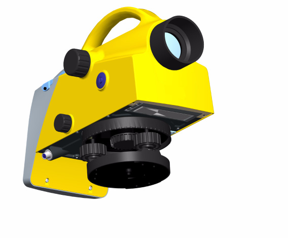
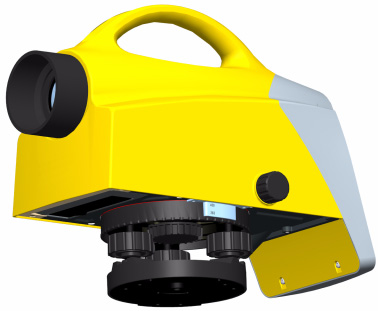
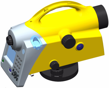
Instrument description
Telescope objective with integrated sun-shield
Telescope focusing knob
Horizontal tangent screw (endless slow motion drive)
11. Window for circular bubble
13. Cap, to be removed for adjustment of circular bubble
18 Trimble DiNi User Guide
Instrument Description 3
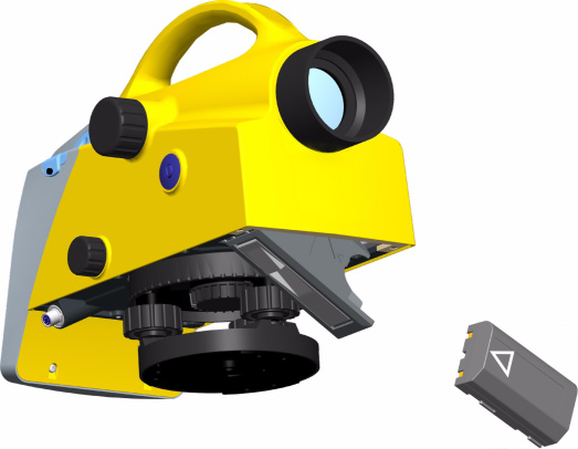
Instrument description, battery compartment
14. Battery compartment
Instrument description, sight vane
15. Sight vane (notch and bead sights)
Trimble DiNi User Guide 19
3 Instrument Description
Software Overview DiNi®
Main Menu DiNi®:
Note – *)Only Trimble DiNi 0.3mm/km
Select from a list of stored projects
Start a new project
Change the name of a stored project
Delete a stored project
Copy information between
Edit stored data, enter and view data and enter and change code lists
Transfer data from the DiNi
to a USB Memory Stick
Transfer data from a USB Memory Stick to the DiNi
Intenal and external memory. Total memory space, free memory space and format internal and external memory
20 Trimble DiNi User Guide
Instrument Description 3
2 Configuration Input
Input of Refraction coeff., Addition const. (R), Date and Time
Input of different Limits and control settings.
Line of sight adjustment.
Nähbauer Method Line of sight adjustment.
Line of sight adjustment.
Japanese Method Line of sight adjustment.
Settings for units in display
and input, displayed last count, sound and language, date*) and time*).
Settings of recording, type of
recording (RMR or R-M), additional data (time*) or temperature*)) and point number increment.
Single Point Measurement
Single point measurement
with height stationing.
Continous measurements
Line Adjustment*)
C CAUTION – When formatting the USB Memory Stick and internal memory all stored data will
Trimble DiNi User Guide 21
3 Instrument Description
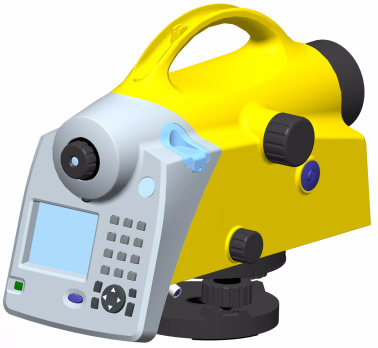
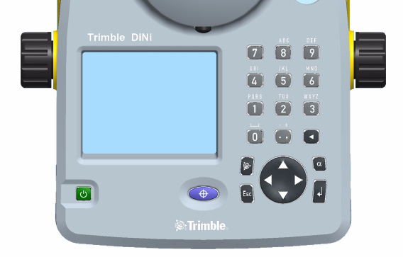
Keyboard and Display Description
Control and display unit of DiNi®
Switches the instrument on or off
Starts a measurement
Navigates through menus, shows drop-down lists and changes check box status
Returns to previous display/menu
22 Trimble DiNi User Guide
Instrument Description 3
Switches the keyboard keys between primary and secondary function. Status are indicated at the top of the display.
Displays the Trimble functions menu
to delete previous input
Primary function: Period and commaSecondary function: Plus and minus (Press multiple times to get correct character)
Primary function: 0Secondary function: Space
Primary function: 1Secondary function: PQRS (Press multiple times to get correct character)
Primary function: 2Secondary function: TUV
Primary function: 3Secondary function: WXYZ (Press multiple times to get correct character)
Primary function: 4Secondary function: GHI (Press multiple times to get correct character)
Primary function: 5Secondary function: JKL (Press multiple times to get correct character)
Primary function: 6Secondary function: MNO (Press multiple times to get correct character)
Primary function: 7Secondary function:
Primary function: 8Secondary function: ABC (Press multiple times to get correct character)
Primary function: 9Secondary function: DEF (Press multiple times to get correct character)
Trimble DiNi User Guide 23
3 Instrument Description
Information regarding current program, input and battery status.
Information regarding workflow status. Sample shows Line levelling
Result of the latest measurement
Input of information connected to the next measurement
24 Trimble DiNi User Guide
Instrument Description 3
Function field and information area.
When all information connected to the next measurement are entered this symbol will appear to indicate that the intrument is ready to measure
This symbol will appear as a reminder when the instrument is set to measure towards an inverted staff.
Trimble DiNi User Guide 25
3 Instrument Description
Principles of Keyboard and Display Functions
Key function and description
Navigate with the r spider key in the display menus to highlight the item you want to select.
To confirm a selection press the
s enter key or go directly by pressing the number of the selection e.g. 1 number 1 key
Some input fields are marked with a drop down-arrow to indicate that input selections are made from a pre-defined list. Press the right arrow on the r spider key to select from a drop-down list, press enter to confirm.
Press the left arrow on the r spider key to step through the possible selections
26 Trimble DiNi User Guide
Instrument Description 3
Key function and description
Some input fields are open for alpha and numeric inputs from the user.
Type in the input of your choice with the instrument keyboard. Switch between numeric, capital letters or lowercase letters by pressing the u alpha key. The status is indicated at the top of the display.
Some inputs are made with a check box.
Navigate with the r spider key in the display to highlight the check box.
Press the left arrow on the r spider key to select or unselect.
Navigate with the r spider key up, down, left or right.
In this part of the display you can navigate with the r spider key up or down through the different input fields and down to the softkeys at the bottom of the display. When an input field is highlighted you can press the right arrow on the r spider key to select from a drop-down list or press the left arrow on the r spider key to step through the possible selections
Trimble DiNi User Guide 27
3 Instrument Description
Key function and description
In this part of the display you can navigate with the r spider key left or right to highlight different soft keys. Press s Enter to select the highlighted soft key function.
To be able to go back up to the input fields you must first highlight the Soft key located directly under the input fields, press up or down on the r spider key
The symbols displayed in the bottom corner of the display indicates the next step.
= Ready to measure
press q / z measurement key
= Press s enter key to selecta detail
= Press s enter key
to store measurement
= Press s enter key
= Press s enter key
= Press s enter key
= Press s enter key
to continue to next
= Press r spider key
up or down arrow to show further data lines
28 Trimble DiNi User Guide
Instrument Description 3
Switching the Instrument On and Off
p switching on and off
A properly charged battery is neccesary for the operation of the instrument. Switch on the instrument with the p key. After a short display of the Logo, the instrument is ready for measurement. The Main menu or the uncomplete application is always displayed.
Trimble DiNi User Guide 29
3 Instrument Description
Correction of the current line of sight inclination by a mechanical compensator
Automatic alignment of the compensator ensures that an inclined line of sight is automatically leveled within the working range both for visual observation and internal electronic measurement. The compensator cannot be deactivated.
The working range of the compensator is ± 15´ with a setting accuracy of ± 0.2" or ± 0.5" depending on instrument type. If the inclination range is exceeded a symbol of a non centered bubble will be shown in the top line of the display.
A warning information is generated and has to be confirmed after releveling the instrument
30 Trimble DiNi User Guide
Instrument Description 3
The compensator has a major influence on the instrument's line of sight. For run centre adjustment, determine the residual line of sight inclination to permit distance-dependent correction of the measured values. For this, the Adjustment menu option on DiNi provides four methods. For precise height measurements, this check should be performed at regular intervals
Angle Measuring System
Angle measuring system
Direct Measurement With DiNi
You can perform simple direction measurements and stake-outs. You can read the direction without any aid by means of an index line on the horizontal circle. The circle is graduated to 1 degree and 1 gon, estimated readings are possible down to 0.1 degrees and 0.1gon
Height/Distance Measuring System
Acoustic Signal Generator
Confirmation of functions and warning signal when system messages are displayed.
Multiple measurements, interims value
Data if a complete measurement
Trimble DiNi User Guide 31
3 Instrument Description
Battery power below 10%
With USB Memory Stick connected
Connect the device or open communication
Disconnect the device or open communication
File operation was successfully
The sound can be activated or deactivate
The permanent memory of the DiNi stores computation constants, operating modes, measuring units, etc. even after instrument shutoff.
The measured data and additional information is stored in the internal memory.
Data Safety
Data storage in the internal memory (non-volatile data memory without buffer battery) offers data safety for unlimited time.
The capacity of the internal data memory depends on the measuring mode, a line leveling with method BFFB will consume more lines then a single measurement.
It amounts to approx. 30 000 data lines.
32 Trimble DiNi User Guide
In this chapter:
Trimble DiNi User Guide 33
An instrument setup with good measuring stability will increase the precision in the measurement result and allow you to utilize the measurement precision of the Trimble DiNi to its full extent.
When a level is setup it is important to consider the following:
Set tripod legs wide apart to increase the stability of the setup. A setup where one leg is placed on e.g asphalt and the other two on soil will still be a stable setup provided that the tripod legs are set wide enough. If it is not possible to set the tripod legs wide apart due to obstacles, then the tripod can be lowered to increase stability.
Make sure that all the screws on the tripod and/or tribrach are tightened to avoid any play.
Any survey quality tripod can be used. However, Trimble strongly recommends the use of tripod heads made of steel, aluminium or similar material. Tripod heads of fiberglass or other composite materials are not recommended.
B Tip – Trimble offers tripod part number 7072550000000 with fixed, non extendable legs. This
tripod is recommended in some regions for leveling highest order lines.
34 Trimble DiNi User Guide
Take into account that a level requires sufficient time to adjust to the ambient temperature. The following rule-of-thumb for a high precision measurement applies: Temperature difference in degree Celsius (°C) x 2 = duration in minutes required for the instrument to adjust to the new temperature.
Avoid sighting across fields with intense irradiation by sun light, e.g. at noon.
Setup and Coarse Centring
In order to guarantee the stability of measurement we recommend the use of a Trimble tripod.
Setup and coarse centring
Extend the tripod legs (1) to a comfortable height of observation and fix them using the tripod locking screws (2). Screw the instrument centrally to the tripod head plate (3). The tribrach screws (4) should be in mid-position.
Trimble DiNi User Guide 35
Coarse Centring (Only When Required)
Set up the tripod roughly above the station point (ground mark). The tripod head plate (3) should be approximately horizontal.
Hook the plumb line (5) into the retaining screw and set up the tripod roughly centred above the ground mark.
Leveling and Fine Centring
Levelling andd fine centring
Level the circular bubble (6) by adjusting the length of the tripod legs (1).
Precision leveling
Align the control unit parallel with the imaginary connecting line between two tribrach screws. Level the instrument in the telescope axis (1) and rectangularly to it (2) by means of the tribrach screws. For checking, turn the instrument round the vertical axis in the diametrical position. In any case, the residual inclination should be within the working range of the compensator (± 15´) after having centred the circular bubble.
36 Trimble DiNi User Guide
Fine Centring (Only When Required):
Shift the tribrach on the tripod head plate until the plumb line is hanging centrally above the ground mark; repeat the leveling various times, if necessary.
Visual field DiNi®
Focusing the Cross Hairs:
Sight a bright, evenly coloured surface and turn the telescope eyepiece until the line pattern is sharply defined.
C WARNING – Sighting of the sun or strong light sources must by all means be avoided because
it would cause irreparable damage to your eyes.
Focusing the Target Point:
Turn the telescope focusing control unit until the target point is sharply defined.
B Tip – Check the telescope parallax: If you move your head slightly whilst looking through the
eyepiece, there must be no relative movement between the cross hairs and the target; check focusing, if necessary.
C WARNING – Residual inclinations of the line of collimation remaining after having centred the
circular bubble are eliminated by means of the compensator. But it does not compensate any inclinations caused by insufficient adjustment of the circular bubble or of the line of collimation. For this reason, both adjustments have to be checked.
Switching the Instrument On and Off
To switch the instrument on or off press the p on/off key.
Operating the OFF function unintentionally does not lead to a loss of measured values. The system will ask in case of certain functions, but on principle, all current values (line leveling) are saved in a non-volatile working memory.
Trimble DiNi User Guide 37
The q Trigger key on the keyboard or the z Trigger key on the right side of the instrument will start a measurement.
Trigger key on right sideof instrument
Trigger key on instrumentkeyboard
Triggering measurements
Note – For high precision measurements, Trimble recommends to use the trigger key
on the right side of the instrument. This trigger key is designed to minimize the
influence of any vibrations caused by touching the instrument when pressing the
trigger key to start a measurement.
38 Trimble DiNi User Guide
Configurating the DiNi
In the configuration menu it is possible to set all general instrument settings and make the instrument adjustments.
To configurate the DiNi, select Configuration
Under Input it is possible to set the Refraction coeff., Addition constant (R), Date and Time.
Select Input from the Configuration menu
Key in the Refraction
Refraction coeff.:
coeff., Addition
constant (R), Date and
Addition const.(R):
Time of your choice
and press s enter key to Store.
Trimble DiNi User Guide 39
Limits / Tests
Note – Only for Line Leveling,except the 30cm control
Select Limits / Tests from the Configuration menu
Max. sighting dist.
sighting dist., Min.
sighting height and
Max. sighting height of
Min. sighting dist.
your choice and press
s enter to continue to
Max. sighting height range:0m - 5m
Select Difference from
Station = B1-F1 to
the drop-down list.
B2-F2Measurement = B1 to B2 and F1 to F2
40 Trimble DiNi User Guide
difference of your
choice. Select or clear
the Check 30 cm check box and accept with s enter.
distance of your choice
for a station (back to fore) and for the whole line (total back to fore).
Select Adjustment from the Configuration menu.
The old adjustment value and information are displayed.
Select Curvature and/or refraction correction on or off during adjustment.
Press s enter to Continue
Trimble DiNi User Guide 41
Select Ok to continue
Note – After an
or Cancel to abort the
adjustment is made
line continuation is impossible.
Select the adjustment
For more information
method of your choice.
Select Instrument Settings from the Configuration menu.
Select Height unit.
m=meter
ft=foot (US Survey
foot)
in=inches
Note – It is possible to
enter a single height in
another unit without
changing the default
setting by manually
adding the abbreviation
of the unit after the value.
42 Trimble DiNi User Guide
Select Input unit.
Select the number of
Note – The instrument
decimals that will be
will still measure and save the values with the
displayed, Display (R).
ful number of decimals.
Select 10 min, to
The automatic switch
Off will not work
instrument after 10
minutes without any
Instrument connected to USB Memory Stick or PC.
Select or clear the Sound check box to turn the sound on or off.
Select the display
Languages will be
changed after confirming the selection
Trimble DiNi User Guide 43
Select the Date system.
Select the Time system.
Settings of Recording
Select Settings of Recording from the Configuration menu.
Select or clear the Recording check box to turn on or off the recording.
44 Trimble DiNi User Guide
Select Recording Data.
R-M=Only the
measured values are
saved
RMC=The measured
and calculated values
are saved.
Note – RMC must be set
to be able to adjust the
level line after
measurement
Select Rec. additional
B Tip – Date and
data. Press s enter to
Time will be stored in
continue to Page 2.
instrument, type 0.3mm/km only
Number system Line
The start number will
Enter PNo. Increment
and Start number. Press s enter to confirm and continue.
Number system Single
The start number will
point measurement /
Intermediated sights:
Enter PNo. Increment and Start number. Press s enter to confirm and continue.
Trimble DiNi User Guide 45
The Trimble Functions menu can be reached at all stages by pressing the t Trimble icon key The following functions are available.
Note – All functions are not available at all times, the available functions in the
Functions Menu are related to the selected program.
Press the t Trimble icon key.
Call up Stake out Point
During Line leveling it is possible to stake out a point.
Select SOut.
urther information.
46 Trimble DiNi User Guide
During Line leveling it is possible to measure a single point.
Select InterM.
Sometimes it is necessary to know the distance to the staff before doing the final measurement - e:g. in a Line leveling it is neccessary to know a distance to the staff to adjust the total distance for backsight and foresight.
With the Measure Distance function it is possible measure only the disatnce to a point.
Select Meas dist.
Press the q / z trigger key to measure.
Press v Escape to return to the program.
Trimble DiNi User Guide 47
In some cases, when a digital measurement is not possible, the input of an optical measurement from a metrical staff may become necessary. The readings can then manually be keyed in for this point.
Note – Take into account that an optical measurement is less precise than a digital
measurement and that the adjusting measurement has been carried out electronically
(reticle shifted to the nominal value according to electronic adjustment) - (identity of
electronic and optical horizon).
Select Opt. meas.
Select if you want to key in the Distance value or if you want to use Stadia readings
48 Trimble DiNi User Guide
If Distance is selected, key in the horizontal reading HD and the rod reading R. Press s enter key to Continue.
If Stadia reading is
Stadia readings = The
selected, key in the
readings from the
stadia reading values
and the rod reading R.
Reichenbach stadia
Press s enter key to
Trimble DiNi User Guide 49
Inverted Staff Measurements
Inverted measurements are required for work underground and inside buildings, the staff base is turned upwards. The inverted staff measurement will be set for all measurements made until this setting is changed.
Select staff invers.
Select Yes to confirm
Yes = Inverted staff
inverted staff setting
No = Normal staff
When inverted staff is set an arrow pointing downwards will be shown in the lower right corner of the display.
50 Trimble DiNi User Guide
Repeated measurements (nM) and Standard deviation (mR) can be defined to be sure that the required accuracy is reached.
One measurement only
Performance of all measurements
Performance of measurements until number of repetitions orstandard deviation has been reached
In repeat measurements, the mean values of staff reading and distance and the standard deviation are displayed after each measurement.
If the standard deviation has been defined, at least three measurements are performed.
When the desired standard deviation has been obtained, the process can be stopped, but take into account that vibrations to the instrument by the key depression have to be avoided - otherwise the last value would falsify the result.
The standard deviation can be saved, but must be defined in Setting of recordings.
Note – In this case, line adjustments are not possible.
The number of measurements is always saved.
Select Mult. meas.
Key in the number of
nM = The number of
measurements nM.
measurements that the instrument will make before a result is accepted. Maximum = 10 measurements.
Trimble DiNi User Guide 51
Key in the standard
mR = The maximum
deviation mR.
standard deviation to
Press s enter key to
be reached before a
result is accepted. A minimum of three measurements will be made.
52 Trimble DiNi User Guide
Whenever it is necessary during the measurement alphanumeric text information including date and time can be entered successively.
Select Comments.
Select Input further information
It is now possible to enter alpha and numeric signs
To add current date or time to the information, select Append current date and/or Append current time.
Trimble DiNi User Guide 53
Press s enter key to store the information.
With this command it is possible to document the basic status of the instrument. Data lines with the following contents are then successively recorded:•
Amount of the line of sight correction
Date of last adjustment
Earth curvature / refraction setting - Refraction coefficient
Staff offset/addition constant to quit the instrument information
54 Trimble DiNi User Guide
With the Illumination function it is possible to switch the diplay and/or bubbel illumination On or Off.
Select Illum.
Switch between illumination On Or Off with the s enter key or
A symbol will be
Using the Power Safe
shown as long as the
mode, the instrument
will switch OfF the
illumination after 30 second. The symbol sun will be changed to symbol moon. With the next keypress the light will be On and the function behind the keypress will be ignored
Trimble DiNi User Guide 55
Illumination and Contrast
In this screen it is possible to set the illumination on or off for the display and/or bubble. The brightness of the ilumination, The contrast of the display and Power safe mode.
In the Illumination drop down list it is possible to select if you want illumination on Bubble only, Screen only or Both
To change the brightness of the bubble illumination highlight Brightness bubble and use the right and left arrow on the r spider key to increase or decrease bightness.
To change the brightness of the screen illumination highlight Brightness screen and use the right and left arrow on the r spider key to increase or decrease bightness.
56 Trimble DiNi User Guide
To change the contrast of the screen highlight Contrast and use the right and left arrow on the r spider key to increase or decrease contrast.
Select or clear the Power safe mode check box to turn on or off. press s enter key to confirm your settings
Version and Serial Number
Press y dot/comma key.
The Program version and Serial number are displayed.
Press s enter key to Continue to the Main dialog.
Trimble DiNi User Guide 57
58 Trimble DiNi User Guide
In this chapter:
Trimble DiNi User Guide 59
5 Measuring Programs
Repetition of Measurements
Select the function
Note – The last
field Rpt., press s
measurement can be repeated in each case
enter to confirm.
e.g. line leveling.
In this case, the
Select the function
original data lines are
field Rpt. confirm with
marked with ##### in
the code range of PI and not used for computing.
Select the appropriate
reasonable from a technical point of view, the last station (line leveling) can be repeated as well.
60 Trimble DiNi User Guide
Measuring Programs 5
Search for Reference Heights in the Memory
Key in Point number
Using the input function all fields can be entered
Select from where the
From project offers
reference height is
points in the selected
"working" project. Other projects offers the selection for all other projects
Select the requested
All projects available
in order of created time.
Trimble DiNi User Guide 61
5 Measuring Programs
Key in Data lines. With
The selected project
curser left or right
is visible in the Status
define the search
criteria for the point and define the point.
Confirm the selected
point or search with spider key up and down arrows to find further lines with identical criterias.
62 Trimble DiNi User Guide
Measuring Programs 5
Incremented and Individual Point Number
Key in line incr. PNo
The function allows
Select with cursor left
toggle between the
or right and down incr.
input of incremented
PNo. or indiv. PNo.
and individual point numbers. The incremented number is incremented by your setting, normally 1.
The user has two count systems for incremented point numbers. One for Line leveling points and one for Intermediate points. The start number and the increment has to be defined,After using an individual point number the system will switch to the incremented value used before. In line levelings, the input of the number of the start point and end point is requested. The point number has 8 digits.
Trimble DiNi User Guide 63
5 Measuring Programs
There is a possibility to
add a singe alpha
numeric value or to add
codes apropriate to the
. The point code
entered three codelists.
has 5 digits.
It is possible to add code after code.
Key in a input line
Status line shows the current font.
64 Trimble DiNi User Guide
Measuring Programs 5
Select with Alpha key
Multiple press on the
the alpha input.
keys will produce the appropriate character
Increment will run with the right placed numeric characters only.
Trimble DiNi User Guide 65
5 Measuring Programs
Single Point Measurement (Without Reference Height)
This program can be reached with Main menu, Survey and then Single point measurement.
Single point measurement (without refernce height)
When measuring without reference height, staff readings can be displayed successively and independently of each other. If recording and point number incrementation have been activated, the measurements are stored correspondingly.
HD=Horizontal distance
66 Trimble DiNi User Guide
Measuring Programs 5
Select Survey and Single
The point number and
Point measurement
code entered will be
Enter Point number
stored with the next
and Point code.
Press the q / z trigger key to start the measurement.
Start measurement to
Info shows battery
status and time, date.Rpt. offers repetition
Trimble DiNi User Guide 67
5 Measuring Programs
The individual height differences are measured and added up. When entering the heights of the start and end points, the nominal - actual difference is computed. Intermediate sights and stake out within the line as well as continuing the line are possible.
total height difference
sum of backsight and foresight distances
final difference (if reference heights for start and end points have beenentered)
B Tip – All important settings (point number incrementation, resolution of measured data) are to
be made before starting the line measurement. That refers especially to the saving as relevant aspect for the line adjustment option.
- The DiNi® allows a subsequent line adjustment only when measuring in the level mode.
- To ensure a high accuracy, it is possible to monitor adjustable limits and tests e.g. for sighting distance, sighting heights, station differences and the 30cm interval check.
68 Trimble DiNi User Guide
Measuring Programs 5
Starting New Line / Continuing Line
Select Survey.
Select 2 Line leveling.
When selecting continue an uncompleted line will be automatically continued.
When selecting From project the line number is requested. Each completed line within a project can be continued. A final line adjustment through all data of a line is also possible.
B Tip – In order to minimize potential problems in long lines, we recommend to
insert now and then fixed change points where the line ends and is continued immediately with the "continue line" option. This operation (line end / continuation) does not affect further line computing, but enables you, in case of a problem, to link the possibly lost line to this point and to connect later the partial lines manually (to add them).
Trimble DiNi User Guide 69
5 Measuring Programs
Key in the Line number of your choice.
Select the Measuring
BF and BFFBDiNi 0.3/1.0: BF, BFFB, FBBF, BFBF, BBFF
Select or deselect alternate.
To confirm the inputs on this page and continue to the next page press enter s , Cont.
Select Point number
Select Find to find the
from the drop-down
list or key in the point
number of your choice.
Select From project to select a point number from the present project.
Select Other project to select a point number from another project.
70 Trimble DiNi User Guide
Measuring Programs 5
Select Code from the
Select From list to
drop-down list or key
select a code from a
in the code of your
If Point number is
choosen from a list the benchmark height will be given automatically.
Backsight and Foresight Measurements
Aim and focus the
The symbol on the
instrument to the staff.
right bottom part of
Start a backsight
the display indicates
measurement with the
that the instrument is
ready to measure.
When the backsight
When a measurement
measurement is ready
is ready it will be
the result will be
marked as done and
the number of measurement will increment.
Trimble DiNi User Guide 71
5 Measuring Programs
Select incremented or individual point number.
Select Point number
Select Find to find the
from the drop-down
list or key in the point
number of your choice.
Select From project to select a point number from the present project.
Select Other project to select a point number from another project.
Select Code from the
Select From list to
drop-down list or key
select a code from a
in the point number of
your choice.
72 Trimble DiNi User Guide
Measuring Programs 5
Select Info.
As total sighting
information Date,
distances are known,
the next stations have
to be selected in such a
way that the total
sighting distances Db
and Df are almost
identical at the end of the line.
Select Rpt. if you wish
Repeated Data lines
to repeat the last
will be marked with
measurement or the
5 # and ignored for
Trimble DiNi User Guide 73
5 Measuring Programs
Intermediate Sights in Line Leveling
After backsight measurement (Method BF, BBFF) or complete station measurement (all other Methods including alternated versions) are done (reference height available) Intermediate Sights measurements are possible.
Press t Trimble key and Select InteM (2)
Start the measurement
Start number and
trigger key.
Press v Escape to
settings different to
return to Line leveling
the Line leveling.
Note – The program Line Adjustment will only calculate and improve the
Intermediate points in respect to the respective instrument station.
74 Trimble DiNi User Guide
Measuring Programs 5
Stake Out in Line Leveling
After backsight measurement (Method BF, BBFF) or complete station measurement (all other Methods including alternated versions) are done (reference height available) Stake out measurements are possible.
Press t Trimble key and Select SOut.
Select Stake Out Point
number from this or
other projects or key in the point number, code and nominal elevation of your choice. Press v Escape to return to Line leveling
Note – The program Line Adjustment will not adjust and change the Stake Out
heights.
Trimble DiNi User Guide 75
5 Measuring Programs
Selectable and Automatic Controls During Line Leveling
It is possible at every station to see the total sigthing distances. Select Info and press s enter key.
The total sighting
Note – As total sighting
distances are displayed
distances are known, the next stations have to be
as Db and Df. Press s
selected in such a way
enter key to Continue.
that the total sighting distances Db and Df are almost identical at the end of the line.
76 Trimble DiNi User Guide
Measuring Programs 5
Automatic Controls
To set up automatic
automatic controls
Maximum sighting distance
Minimum sighting height
Maximum sighting height
Maximum station difference or double measurement difference(e.g. in BFFB)
Check up for the 30cm interval.
The instrument will warn the user when a measurement is outside the set limits.
Press No to accept measurement or Yes to repeat measurement
Trimble DiNi User Guide 77
5 Measuring Programs
Ending a Leveling Line
Select Yes at a point with a known height.
Select No at a point with a unknown height
78 Trimble DiNi User Guide
Measuring Programs 5
With Known Height
If at this station the
enter Point number,
start point number
Code and Benchmark
were entered, the
height from your choice
program will take all
data (height, code)
select from the memory a known point with
from this point (Slope
Point number, Code
and Benchmark height.
Select Cont. to continue
Select Cont. to finish
Sh: total height difference:Db,Df:sum of backsight and foresight distances dz:final difference because entering the benchmark heights.
With Unknown Height
Selct Cont. to finish the
Sh: total height difference Db,Df:sum of backsight and foresight distances
Trimble DiNi User Guide 79
5 Measuring Programs
After a backsight measurement of a point with known height, the heights of discretionary points are determined.
Intermediate sights
Z=Height of intermediate point
h=Height difference between new and backsight point(for display only)
80 Trimble DiNi User Guide
Measuring Programs 5
Select Survey and Intermediate Sights
Select Point number
Select Find to find the
from the drop-down
list or key in the
number. Select From
benchmark point with
project to select a
number, code and
point number from
height of your choice.
the present project. Select Other project to select a point number from another project
Press s enter key to
Selected benchmark
points can be modified in number and code.
Aim and focus the instrument to the staff at the benchmark.
Start the measurement with the q / z trigger key.
Trimble DiNi User Guide 81
5 Measuring Programs
Accept the measurement to benchmark point or repeat the measurement.
Key in the point
Incr./Indiv: Define
number and code for
PNo: Select Find to
Start the measurement
find the next free
point number.
trigger key.
Code: Select from a list
Key in the point
Result of new point
number and code for
Select Disp to change
next new point.
Start the measurement
Select Rpt. to repeat
trigger key.
Press v escape key Select Yes and press s enter key to end the program.
82 Trimble DiNi User Guide
Measuring Programs 5
Stake Out
Stake Out
After the measurement of a point with known height, the heights of the points to be staked out (approximate points) and the differences between nominal and actual values are determined. The staff is shifted until the difference measured between the nominal and actual values has been reduced sufficiently.
Znom=102.000000 m
dz:Setting out difference (nominal - actual)
Trimble DiNi User Guide 83
5 Measuring Programs
Select Survey and Stake out.
Select Point number
Select Find to find the
from the drop-down
list or key in the
number.Select From
benchmark point with
project to select a
Point number, Code and
point number from
Benchmark height of
your choice.
project.Select Other project to select a point number from another project.
Press s enter key to
Selected benchmark
points can be modified in Point number and Code.
Aim and focus the instrument to the staff at the benchmark.
Start the measurement with the q / z trigger key.
84 Trimble DiNi User Guide
Measuring Programs 5
Accept the measurement to benchmark point or repeat the measurement.
Select Point number
Select Find to find the
from the drop-down
list or key in the Point
number, Code and
Select From project
Benchmark height for
to select a point
the Stake out point of
your choice.
present project.
Select Other project to select a point number from another project.
Press s enter key to
Selected Stake out
points can be modified in Point number and Code.
Trimble DiNi User Guide 85
5 Measuring Programs
Measurement to Digital Graduation of Staff
Aim and focus instrument to staff at Stake out point.
Start the measurement with the q / z trigger key.
Select accept and press
According to the
s enter key to confirm
deviation dz, staff
and save the result.
will be shifted and measurement repeated until dz has been reduced sufficiently
Select Down arrow and press s enter key to call up the next Stake out point or press v escape key to key in the next Stake out point or use Search to define the next search criteria.
Tip – When calling the heights to be staked out from a project in instrument
memory, the address of the last height just staked out appears after the
result has been confirmed. By pressing r spider key down arrow and
Accept this value, the next height to be staked out can be called
immediately, provided that the heights have been stored in the desired
order in the project. By pressing v escape key it is possible to return to the
menu to enter heights and call up search.
Tip – With Search a search criteria for the next Stake out point can be
defined.
86 Trimble DiNi User Guide
Measuring Programs 5
Stake Out With Metrical Graduation of the Staff
Staff carrier turns staff with metrical graduation towards the observer and receives instruction for height adjustment of staff.
To release the control
staff carrier turns staff
measurement start a
measurement with the
graduation towards
the observer and
receives instruction for height adjustment of staff. After height adjustment of the staff, carrier turns staff with code graduation to observer.
Select accept and press
Select Disp to change
s enter key to confirm
and save the result.
Press v escape key, select Yes and press s enter key to discard the stake out measurement.
Press v escape key, select Yes and press s enter key to end the stake out measurement.
Trimble DiNi User Guide 87
5 Measuring Programs
Line Adjustment (For Instrument Type 0.3mm/km Only)
In line leveling, a line is linked to points with known heights at the beginning and at the end so that the measured height difference can be compared with the nominal height difference.
The "line adjustment" program allows to spread the occurring difference over the individual staff stations proportionally to the sighting distances, obtaining adjusted heights as result. During this operation, the measured values (staff readings, distances) are not changed. Intermediate sights are only improved according to the improvement of the respective instrument station.
Line adjustments can only be performed if the leveling line has been completed and saved on the memory along with the intermediate heights.
It may happen that the definite heights of backsight points are not yet known when the line is measured. In this case, the nominal height values can be entered during the line adjustment. It is also possible to adjust loops. Loops are leveling lines with identical start and end height.
Requirements for a line adjustment:
The entire leveling line has to be recorded in one project.
Set in any case the recording mode RMC.
Otherwise line adjustment will not be possible, as in the project no space is
reserved for the adjusted heights.
While measuring a station, the leveling line must not be interrupted in such a way that measurements are skipped.
The common adjustment of successive partial lines is only possible if they are linked by the "continue line" option.
But they can be positioned in chronological order at different spots in the project. Different partial lines started in each case with "new line" can only be adjusted separately.
Line adjustment does not include averaging between fore and back reading.
Line adjustment cannot be repeated.
Before starting line adjustment, make sure the battery is sufficiently charged.
The data stored on memory must not be changed between line measurement and line adjustment.
(Before line adjustment is actually started, the leveling line is checked by recalculating the measured line. The program accepts the following differences between original and recalculated values:
88 Trimble DiNi User Guide
Measuring Programs 5
In the Main dialog select Calculation.
Select Line Adjustment.
Selcted the project to
The program offers
be adjusted and press
the "working" project
as default. All lines in
all projects are adjustable.
Define the search
Search is available
criteria and enter the
with Point number,
value of your choice.
Point code, Line
Press s enter key to
number and Memory
Trimble DiNi User Guide 89
5 Measuring Programs
Select Accept and press
s enter key to accept the proposed line.
Press r spider key up or down arrow to search for lines with the same criteria.
Select Ok and press s
The program will find
enter key to continue.
automatically the end of this line and all the continuations.
Program will inform about the data lines for the choosen Line.
Key in or confirm the proposed Benchmark heightspress s enter key to continue.
Key in or confirm the
Changed point code
proposed Code for the
helps to identify the
changed Benchmark
changed heights.
heights.
press s enter key to Continue.
Press s enter key to
Helps to identify
human errors in this process
90 Trimble DiNi User Guide
Measuring Programs 5
Press s enter key to Accept.
Press s enter key to
Program checks the
data lines for changes. With changed data line (heights) the line adjustment is impossible.
Finalize the adjustment by pressing s enter key to End.
Trimble DiNi User Guide 91
5 Measuring Programs
92 Trimble DiNi User Guide
In this chapter:
Trimble DiNi User Guide 93
6 Measuring Function
Measuring Principles and Components
DiNi height measurement
The method of single interval measurement is used to determine the height value (comprising a code and interpolation value) on the basis of 15 two-centimetre intervals of the staff and to average the results. For perfect recognition of the intervals and the coded information which they contain, it is essential that the staff image be accurately focused on the instrument cross-hairs. The usual fluctuations in focusing does not influence the measurement result.
DiNi distance measurement
In the DiNi, the distance to the staff is computed together with the determination of the height. This distance is the horizontal distance between the vertical axis of the instrument and the plane of the graduation of the staff (not the centre of the staff base).
Staff section in the leveling mode
For the determination of heights and distances on the DiNi, the instrument only requires a 30 cm staff section positioned symmetrically to the sighting axis. To ensure optimum measurement results, this staff section must be free from interruptions. Normally this can be easily checked in the eyepiece. For sighting distances of less than 14 m, however, a staff section larger than the visible one is evaluated. If the staff section is interrupted (e.g. by branches) or if measurements are taken beyond the base or top of the staff, the evaluated staff section is no longer symmetrical to the sighting axis.
Since major asymmetries may impair the measuring accuracy, measurement is blocked if obstacles cover more than a few centimetres beyond the cross-hairs (error message: "out of measuring range").
For distances between the minimum sighting distance and a few meters, the instrument only requires a staff section of 10 cm. Due to this minimum measuring section, a range of approx. 6 cm from the beginning and end of the staff is not read for the shortest sighting distance.
Staff code
The staff code consists of 2 cm intervals filled white (yellow) / black or half white (yellow) / half black. For height and distance measurements, only the edges of the 2 cm intervals are used. Thus, necessary controls of invar staves are made easy. The precision code consisting of 1 mm wide lines is only used for decoding purposes in case of sighting distances of less than 6 metres.
94 Trimble DiNi User Guide
Measuring Function 6
Pendulum stop
If the pendulum is at its stop, measurement cannot be started. If the pendulum reaches its stop in the measuring process, the measurement is stopped and error message "compensator out of range" is displayed.
Light conditions
Direct solar irradiation in the telescope must be avoided as this may be harmful to the eye and may cause failure of the measurement. If sun reflections are visible in the telescope (sun low on horizon), shade the telescope with your hand until the reflections disappear. In the case of sun reflections on the staff, turn the staff sideways until the reflections are no longer visible to the observer.
strong light
If measurements are performed against strong light, the measuring time may be increased and the accuracy of the measured data may be reduced.
variation in brightness / overexposure
If variations in brightness during the measuring process lead to overexposure of individual measurements (the sun comes out) , the measurement is automatically restarted. If this situation occurs repeatedly, measurement is stopped with error message "Change in brightness too great".
It can then be started again.
twilight / insufficient illumination
If the measuring signal in twilight is too weak for reliable measurement, if the staff section available is not sufficient for measurement or if no staff has been sighted, error message "Staff cannot be read" is displayed. If the brightness is just about sufficient for measurement, the measuring time may be markedly increased. Should the resulting measuring times exceed 5 seconds, reduced accuracy of the measured data must be expected. In such cases, it is advisable to illuminate the staff.
staff illumination
If the staff has to be illuminated, we recommend to use a fluorescent lamp installed laterally in front of the staff beside the graduation. If the lamp is placed approximately at the height of the line of sight, a 10 W lamp (12 V, 220 V) will do. Directional light, e.g. by using an accumulator lamp, is not recommendable due to inhomogeneous illumination, formation of shadows or reflexes which could lead to errors of measurement.
Measuring beam interruption
In sunlight, a short interruption of the measuring beam is of virtually no importance, due to the short exposure times. If the measuring beam is interrupted by traffic and measurements are lost, the measuring time will be extended accordingly.
Trimble DiNi User Guide 95
6 Measuring Function
The displayed reading is a mean value obtained from several measurements. In the case of major differences between the individual measured values, the measurement is rejected and error message "Standard deviation out of range" is displayed. This only eliminates gross errors; an assessment of the quality of the measured data is not made. In the case of vibrations or air turbulences, it has been found that the measurements displaying the smallest deviations need not necessarily provide the best measured data.
Multiple Measurement
We recommend to use the multiple measurement option in such cases. Avoid triggering a measurement in moments of strong vibration, e.g. when a heavy vehicle is passing. This can be visually checked.
5 m telescopic staff
DiNi instruments provide measurements with DiNi code staves of up to 5 m length. For this, the 5 m telescopic staff Td 24 and TD 25 are available. For the measurements all staff sections below the measured height value must be slid out and locked. If you take measurements with the staff being pushed in either partially or completely, for example as you do not need the full length of the staff, make sure not to sight at the pushed in section of the staff. Otherwise, erroneous measurements or nonsensical results cannot be precluded.
96 Trimble DiNi User Guide
Measuring Function 6
Hints for Precision Measurements
A digital level is an optical level with automatic data logging, data storage and data processing. For this reason, the marginal conditions to be observed when using a digital level are the same as with an optical level.
Hints for Precision Leveling
Do not expose tripod and instrument to one-sided irradiation by sun light. Avoid sighting across fields with intense irradiation by sun light, e.g. at noon.
Take into account that also digital levels require sufficient time to adjust to the ambient temperature. The measurement applies: Temperature difference in Kelvin x 2 = duration in minutes required for the instrument to adjust to the new temperature. For measurements of normal accuracy, e.g. using foldable staves, at least half the above duration should be considered for temperature adjustment.
The DiNi instruments are equipped with a temperature sensor. The temperature gradient of the line of sight of the instrument is determined and stored by the factory. The instrument carries out the necessary improvement of the line of sight immediately during the measurement. This correction is only possible in instruments completely adjusted to the ambient temperature and, consequently, does not make the temperature adjustment unnecessary.
Equal sighting distances shall by all means be kept to eliminate possible variations of the line of sight by temperature, mechanical stress and instrumental effects (focusing lens).
Do not choose sighting distances that are considerably longer than 30 m.
To obtain the specified accuracy of the instrument and eliminate the residual compensator error, make sure the circular level has been adjusted well and apply one of the following methods for measuring:
Measurement according to an alternate method, known as "red trousers" method (BFFB,FBBF)
Measurement according to a non-alternate method (BFFB,BFFB) after measuring B,F, readjust the circular level with orientation to foresight.
Before triggering a measurement, make sure that vibrations and shocks transmitted to the instrument e.g. from passing heavy vehicles or strong gusts of wind have settled (check by viewing through telescope or decide by experience).
Use selectable and automatic controls during Line leveling. These warnings offer the possibility to repeat or use the readings. Under all these circumstances the reading may still be possible, but these tests offer the user the possibility to ensure the highest accuracy in the appropriate application.
A warning can be set to avoid measurement to the lowest part of the staff (ground refraction).
Trimble DiNi User Guide 97
6 Measuring Function
A warning can be set to avoid measurement to the upper part of the staff. This feature is only recommended for highest precision in case of permanent measurement at the upper end of the staff (e.g. in a tunnel).
A check can be made to ensure that a full 30cm of the staff is visible, equally spaced around the horizontal cross hair. This feature is only recommended for highest precision in case the 30cm section may be partially obscured by obstuction.
Underground, Staff Sinking Into the Ground, Vertical Positioning,
Turning
similar to optical levels.
Invar Staves
On request there is a staff certificate, which describes the staves. The staves have to be used, transported and stored properly and to be calibrated in corresponding time intervals.
Hints for Precision Measurement - Area Leveling
For precise area leveling, the adjustment of the line of sight is of great importance due to the different sighting distances. In line leveling, the possible inclination of the horizon is eliminated by equal sighting distances. For precise area leveling, the adjustment of the instrument prior to the measurement is absolutely advisable. In measurements carried out throughout the day, with great temperature differences between the beginning and end of measurements and additionally strong irradiation by sunlight, the internal temperature correction system of the instrument eliminates the main part of the variations of the line of sight. But to make sure, comparison measurements to fixed points should be made and readjustments should be carried out in between, if necessary.
98 Trimble DiNi User Guide
In this chapter:
Trimble DiNi User Guide 99
7 Data Management
DiNi offers a project (files) oriented data storage. Data are stored physically in the internal memory in an internal data format. The data can be transferred directly via Cable to PC or to a USB Memory Stick. During transfer of the data the format will be changed to the common ASCII format M5, thus backwards compatible to the former DiNi Series is guaranteed. The exported project will have the unit of measurement in relation to the current setting (Configuration, Instrument settings Height unit).This allows exporting the file in different units of measurement appropriate to the users chooses.
Via USB Memory Stick
100 Trimble DiNi User Guide
Data Management 7
The submenu allows select, create, delete and rename projects. Additionally the content from a complete project can be copied in another project.
In the Main dialog select Files.
Select Project menu.
Trimble DiNi User Guide 101
7 Data Management
Select a Project
Select Select project (1)
Highlight the requested
All projects are
project from the project
available in the
list and press s enter
chronological order
key to select.
they were created.
Selected project will be displayed in Main Menu and most of the surveying menus
102 Trimble DiNi User Guide
Data Management 7
Create a Project
Select New project.
Key in the project
Input fields are open
Name of your choice.
for alpha and numeric
You can also key in the
Operator name and
Name field is limited
Press s enter key to
Store the project.
compatibility to older
The project can now be
selected from the project list
Trimble DiNi User Guide 103
7 Data Management
Rename a Project
Select Rename project.
Select the requested
All projects are
project and press s
available in the
enter key to Select.
chronological order they were created.
Key in the new project
Input field are open
name and press s
for alpha and numeric
enter key to Store.
Press v escape key to
The change will be
return to the project
shown in the project
104 Trimble DiNi User Guide
Data Management 7
Delete a Project
Select Delete project.
Highlight the requested
All projects available
project and and press
in order of created
s enter key to Select.
Select Yes and press s enter key to delete the selected project.
Select No and press s enter key to escape.
Select next project to be deleted or and press
v escape key to return to the project menu.
Trimble DiNi User Guide 105
7 Data Management
Copy Between Projects
Select Copy between projects.
Highlight the source project and press s enter key to select.
All Data lines will be transferred between Data line 1 and Data line 2.
Before final accepting the data line will be shown in the Editor screen, the selection can be still changed.Same procedure for the Data Line 2
106 Trimble DiNi User Guide
Data Management 7
Select Yes to confirm or No to escape.
Confirm the selection from line to line
The process will then
destination project and
run without any user
press s enter key to
Trimble DiNi User Guide 107
7 Data Management
The Editor allows searching data lines for viewing and changing, input data lines (Height, Point number and Code), delete data lines and creating or modifying the three code lists
In the Main dialog Select Files.
Select Editor.
108 Trimble DiNi User Guide
Data Management 7
Searching Data Lines
Select Data? from the drop down list.
Select View and press
s enter key to Continue.
Select Search and press
The last data line of
the project will be
Select Data lines from the drop down list.
Select Point number, Point code, Memory address or Line number. Press s enter key to Continue.
Trimble DiNi User Guide 109
7 Data Management
Key in the Point number press s enter key to Continue.
Press r spider key up
The program will not
or down arrow to
allow changing of the
search for lines with
measurement values!
identical criteria. Select Change to change Heights, Point numbers and Codes
Deleting Data Lines
Delete all Data
Select Data? from the drop down list.
Select Delete and press
s enter key to Continue.
110 Trimble DiNi User Guide
Data Management 7
Select Delete all data.
Select Yes and press s enter key to delete all data in the address range.
Trimble DiNi User Guide 111
7 Data Management
Deleting Selected Data Lines
Select Data? from the drop down list.
Select Delete and press
s enter key to Continue.
Select Select data.
Select search criteria from Data line 1 drop down list press s enter key to confirm.
Key in the Address and press s enter key to confirm.
Press s enter key to Continue.
Select Accept and press
s enter key to confirm.
112 Trimble DiNi User Guide
Data Management 7
Select search criteria from Data line 2 drop down list press s enter key to confirm.
Key in the Address and press s enter key to confirm.
Press s enter key to Continue.
Select Accept and press
s enter key to confirm.
Select Yes and press s
Note – All data from
enter key to confirm.
address 21 to 42 will be deleted.
Trimble DiNi User Guide 113
7 Data Management
Input of Data Lines
Select Data? from the drop down list.
Select Input and press
s enter key to Continue.
Key in Point number,
Point number - Select
Code and Benchmark
Find to find the next
height. Press s enter
free point number.
key to Store the values.
Code - Select From list
When all points have
to select a code from
been entered press v
escape key to return to the Editor.
114 Trimble DiNi User Guide
Data Management 7
Creating or Modifying the Three Code Lists
Select a code list from the drop down list press s enter key to confirm.
Overview about current list content
To change the name, highlight Name and press s enter key.
Enter the new name of the code list and press
s enter key to Continue.
Trimble DiNi User Guide 115
7 Data Management
To insert a new item, highlight Ins and press
s enter key.
Select an entry in the list. Highlight Del and press s enter key.
Select Yes and press s enter key to continue or select No and press s enter key to abort.
To change an items order in the list, select the item in the list by pressing the r spider key up or down arrow. When the item is highlighted select the Move Up or Move Down arrow press s enter key to move the item in the list
Highlight End and press s enter key to confirm all the changes.
116 Trimble DiNi User Guide
Data Management 7
DiNi to PC
Connect PC via cable PN 73840019 to the Trimble DiNi.
Start Trimble Data transfer at the PCUse Device "DiNiUSB"
Use the "Receive" tabSelect the files for transferring to PCDefine the folder at the PC and start the data transfer.
Trimble DiNi User Guide 117
7 Data Management
PC to DiNi
Use the "Send" tabSelect the files for transferring to DiNiStart the data transfer.
118 Trimble DiNi User Guide
Data Management 7
DiNi to USB Memory Stick
Note – While a
Memory Stick via
measurement runs, the instrument will reject the
cable PN 73841019 to
possibility for this menu!
the Trimble DiNi. The
It is possible to open the
instrument offers the
menu after the
possibility to open the
measurement via the known workflow.
menu for Data import and export directly.
The instrument allows
Note – If the name
copying files in both
already exists, the instrument will offer the
possibility to copy the file
under a new name.
Note – Before data
transfer the program will
check the free space and
reject the activity in case
of less memory. Please
accept unused space for
data security.
Note – The program will
inform and reject an
empty file.
Trimble DiNi User Guide 119
7 Data Management
Select Files and Memory
Select Format Internal
Note – Internal memory
Memory or Format
and external memory is not comparable. The data
External Memory,
are stored in an own
press s enter key to
compressed format in the
instrument. The file size will be internally about 50% of the file size under an Office PC System.
Select Yes and press s
C CAUTION – All
enter key to confirm.
data in the internal memory will be erased.
Select Yes and press s
C CAUTION – All
enter key to confirm.
data in the external memory will be erased.
C CAUTION – When formatting the USB Memory Stick and/or internal memory all stored data
will be lost.
120 Trimble DiNi User Guide
Data Management 7
Data Format
The M5 Data Record Format
All 5 data blocks are preceded by a type identifier. The 3 numerical data blocks have a standard layout comprising 14 digits. In addition to the decimal point and sign, they accept numeric values with the specified number of decimal places. The information block is defined by 27 characters. It is used for point identification (PI) and text information (TI e.g.).
The address block is comprised of 5 digits (from address 1 to 99999).
The M5 Data Line
The data line of the M5 format consists of 121 characters (bytes). The multiplication of this figure by the number of addresses (lines) stored shows the size of the project file in bytes.
Blanks are significant characters in the M5 file and must not be deleted.
The example describes an nine M5 data lines from address 164 to 172. Column 119 includes a blank (no error code).
The end of the line has CR, LF (columns 120 and 121, shown here as <= ).
Trimble DiNi User Guide 121
7 Data Management
Carriage return<, Line feed
Block5 value block
Type identifier5 for block5
Block4 value block
Type identifier4 for block4
Block3 value block
Type identifier3 for block3
Information block
Type identification2, Trimble DiNi is using TO, KD1 and KD2
Memory address of data line
Type identifier1 Adr for address
Defines M5 format
122 Trimble DiNi User Guide
Data Management 7
Explanation to the data line
Format identifier M5
5 meas. data blocks
Address identifier
Information block
ASCII code
CR (Carriage Return) 1
The Text Information in the M5 Format
The information block has 27 characters.
Trimble DiNi User Guide 123
7 Data Management
The Type Identifier in the M5 Format
In the course of the time, requirements on the data format have increased. Therefore, the M5 Format carries most of the type identifiers of all available formats, always based on the preceding format.
Type identifiers are defined by two characters (except for Adr). If only one character is necessary, the second character is a blank.
In the M5 Format there are 5 Type identifiers (TK) defined:
TK1: Adr Identifier address (Value1)
TK2: T2 Identifier information (Value2)
TK3: T3 Identifier 3. Value field (Value3)
TK4: T4 Identifier 4. Value field (Value4)
TK5: T5 Identifier 5. Value field (Value5)
"KD" for point identification, "TO" for text information, "R", "HD", "Z" for T3, T4, T5.
Definition of the Type Identifiers
Type identifiers are assigned to the 5 measuring data blocks of pre-set codes, which show the number or character value of the block.
Type identifiers are (except for Adr) defined with two characters. If only one character is necessary, the second character is blank. The code is case sensitive.
Type Identifiers - Formats M5
TI in Display TI in Record Designation
Single staff reading
Staff reading in backsight
Staff reading in foresight
Staff reading in intermediate sight
Standard dev. of mean staff reading (in multiple meas.)
number of measurements (in multiple measurements)
nominal standard deviation (in multiple measurements)
Height of backsight point
Height of point measured in foresight
Height of intermediate sight
124 Trimble DiNi User Guide
Data Management 7
TI in Display TI in Record Designation
Instrument height (equal to sight. h.)
Nominal height/closing height
Height difference of a station or height difference from previous measurement
Height difference of complete line
Setting out difference (nominal-actual)
Closing difference of line (nominal-actual)
Backsight distance
Foresight distance
Intermediate sight distance
Mean value of backsight distance (for display only)
Mean value of foresight distance (for display only)
Reading from the lower Reichenbach stadia line
reading from the upper Reichenbach stadia line
Total of backsight distances
Total of foresight distances
Line of sight error
Refraction coefficient
Point number recorded in information block
Point Code recorded in information block
Line number recorded in information block
Station number recorded in information block
Text information, general
Point identification
Note – Values which are neither displayed nor recorded are marked by a dash (-). The
Db and Df data refer to the last station completed.
Trimble DiNi User Guide 125
7 Data Management
Recording Data and Data Lines With DiNi
Content of Record
Content of PI
Single Point .
after line interupt.
Intermediate sight.
End of interm. sight.
Stake out diff., nom. height
Check measurement
126 Trimble DiNi User Guide
Data Management 7
Content of Record
Content of PI
Nominal closing height
Actual closing height
Intermediate Backsightsights and Stake out
backsight meas.
before input data
- Measuring units,
- Adjustment and - Input
The recording data line "Optical measurement " refers to the next measurement even if it is not recorded in the following data line.
Trimble DiNi User Guide 127
7 Data Management
128 Trimble DiNi User Guide
Adjustment
In this chapter:
Trimble DiNi User Guide 129
8 Adjustment
Adjusting the Line of Sight
The instrument adjustment defines the necessary corrections for the line sight of DiNi, which are required to ensure optimum measuring accuracy. Increased strain placed on the instrument by extreme measuring conditions, transportation, prolonged storage and major changes in temperature may lead to misalignment of the instrument and faulty measurement results, particularly in case of different distances from instrument to staff. Adjusting the line of sight and defined measurement methods eliminating these errors.
Calling up the Adjustment Function
Select Configuration from the Main Dialog
Select Adjustment from the Configuration menu.
The old adjustment value and information are displayed.
Select Curvature and refraction correction on or off during adjustment.
Press s enter to continue
130 Trimble DiNi User Guide
Adjustment 8
Press Ok to continue or
Note – After an
Cancel to abort the
adjustment is made
line continuation is impossible.
Select the adjustment method and press s enter to continue
Set up two rods (A,B) roughly 45 m apart. Divide this distance into three and define 2 instrument stations (1,2) about 15 m away from the rods on the connecting line between them. Measure both rods from each of these stations.
Trimble DiNi User Guide 131
8 Adjustment
Define a distance of approx. 45 m length and divide it roughly into three. Create an instrument station (1,2) at either end and set up a staff at each point marking one third of the connecting line (A,B). Measure both rods from each of the instrument stations.
Set up 2 rods (A, B) roughly 20 m apart. First measure these rods from instrument station (1) located midway on the connecting line between the two rods. Then repeat the measurement from instrument station (2) which is located on the elongation of the two staff stations approx. 20 m outside the defined distance.
Kukkamäki method
132 Trimble DiNi User Guide
Adjustment 8
This method is largely identical with the Kukkamäki method. With this method, however, the distance between the rods should be about 30 m with station (2) being about 3 m behind staff A.
Making the Adjustment
C CAUTION – Before starting any adjustment, allow the instrument to adapt to the ambient
temperature and make sure it is protected against heating up on one side (sun radiation).
C CAUTION – After the selection of the adjustment method, you can change the settings of earth
curvature and refraction. This is not possible at another point of the DiNi menu system. Changes of earth curvature and refraction settings become effective only if you adjust the system afterwards. The line of sight will then be corrected accordingly.
It may become necessary to correct the staff reading for earth curvature, if you must
take measurements with different sighting distances and correction is not provided by
the evaluation program used. General application of refraction correction is
controversial. It is, however, possible on DiNi instruments. You can change the
coefficient of refraction in the Input menu. If you set the coefficient to zero, the
correction of refraction will be inactive.
Select the method of your choice. In this example we will show the Förstner method.
Aim and focus the
B Tip – While the
DiNi at staff A from
adjustment measurement a
position 1, press z to
measurement should be used.
Trimble DiNi User Guide 133
8 Adjustment
Aim and focus the
Disp. offers the
DiNi at staff B from
possibility to show at
position 1, press z to
every step all done
Aim and focus the DiNi at staff B from position 2, press z to measure.
Aim and focus the DiNi at staff A from position 2, press z to measure.
The result of the
Select Inp. to input a
adjustment will be
value estimated by
To accept the new
value select New and
Select Old to keep the
confirm with s enter.
old values and abort the adjustment.
Select Rpt. to repeat the adjustment.
Select Disp. to see all measured values.
134 Trimble DiNi User Guide
Adjustment 8
Turn the staff A around or replace it with a metric graduated staff and compare the reading with the specified value R. If the difference exceeds 2 mm, the reticule position needs to be aligned.
Remove cap and adjust the setting screw below
C CAUTION –
the eyepiece until the
Make sure that the
actual and nominal
cap is fixed again
readings are identical.
after this procedure.
Various adjustments of lines of sight carried out successively should differ only by some seconds. Prerequisites for reaching this result are stability of installation and unchanged environmental conditions. We recommend to prepare a set of chronological statistics including the adjustment values. In case of inexplicable differences within short periods, provided the measuring conditions remained unchanged, a workshop should be consulted.
c_ ["]
31 Dec 05 Jan 10 Jan 15 Jan 20 Jan 25 Jan 30 Jan 04 Feb 09 Feb
Trimble DiNi User Guide 135
8 Adjustment
Check the Function of Circular Bubble
Automatic alignment of the compensator ensures that an inclined line of sight is automatically leveled within the working range both for visual observation and internal electronic measurement. When turning the instrument round the vertical axis, the circular bubble has to remain within the adjustment circle.
In precision measurements, the running centre of the circular bubble has to be in the centre of the adjustment circle. In case of any visible change readjustment is required.
Level the instrument with the 3 tribrach screws until the circular bubble runs centrally to the adjustment circle.
Circular bubble check step 1
By turning the instrument 180° round the vertical axis the circular bubble has to remain within the circle
Circular bubble check step 2
If the circular bubble left the adjustment circle it is necessary to adjust the circular level.
136 Trimble DiNi User Guide
Adjustment 8
Adjustment of Circular Bubble
Removing the circular bubble protection cap.
Trimble DiNi User Guide 137
8 Adjustment
Position 1
Remove the screw (2) of the protection cap with the adjusting tool and detach the protec
Level the instrument with the 3 tribrach screws,Position 1.
Turn the instrument 180° round the vertical axis into position 2.
Eliminate half the residual deviation of the circular bubble by means of the tribrach screw and half by adjusting the circular bubble with the adjustment screws J1, J2, J3.
Repeat this procedure and check the residual deviation.
Fix the protection cap again. Make sure that the rubber joint is placed in the groove.
Position 2
138 Trimble DiNi User Guide
In this chapter:
Trimble DiNi User Guide 139
Technical Data DiNi®
Accuracy as per DIN 18723
Standard deviation on 1 kmof double levelingElectronic measurement:
- invar precision bar code staff
- foldable bar code staff
Visual measurement
- foldable staff, metric scale
Electronic measurement
- invar precision bar code staff
- foldable bar code staff
Visual measurement
- foldable staff, metric scale
Accuracy of distance measurement
Electronic measurement with a 20 m sighting distance- invar precision bar code staff
- foldable bar code staff
Visual measurement:- foldable staff, metric scale
Least display unit
Height measurement
0.01 mm//0.0001 ft/
0.1 mm//0.001 ft/0.001 in
Distance measurement
Electronic measurement
Field of view at 100 m
Electronic measurement field at 100 m
Inclination range
8'/2 mm with illumination
240(W) x 160(H) pixel ; Black/White ; with illumination
140 Trimble DiNi User Guide
Technical Data DiNi®
Type of graduation
400 grads and 360 deg.
Graduation interval
1 grad and 1 deg.
Estimation down to
0.1 grad and 0.1 deg.
19 keys, incl. 1 spider key for navigation
Single measurement
measurement with
with and without
Line leveling with
Line leveling with
intermediate sight
intermediate sight
aBF, aBFFB, aBFBF,
Measured data correction
Compensation of earth curvature and refraction
up to 30000 data lines
USB Interface for Data transfer to PC
USB Flash drive support
Real-time clock and temperature sensor
Recording of time or
Power supply
Internal battery, Li-Ion 7.4 V 2.4 Ah for three days
working time without il umination
-20 °C to +50 °C
Dust- and waterproofness
155 mm x 235 mm x 300 mm
240 mm x 380 mm x 470 mm
Instrument / case
Trimble DiNi User Guide 141
Formulae and Constants
Correction of Staff Reading and Sighting Distance
L = Lo ± Lx - K1 + K2 - K3
K1 = E2 / ( 2 * R ) earth curvature correction
K2 = rk * E2 / ( 2 * R ) refraction correction
K3 = c_ * E / 206265" line of sight correction
uncorrected staff reading
line of sight correction in ["]
staff offset ( + Lx in normal measurement, - Lx in inversemeasurement)
earth radius, R = 6380 000 m
refraction coefficient
uncorrected sighting distance
distance addition constant
Computation of the Line of Sight Correction
c_= (( La2 - Lb2 ) - ( La1 - Lb1 ))/(( Ea2 - Eb2 ) - ( Ea1- Eb1 )) * 206265 ["]
If refraction and/or earth curvature correction are activated prior to adjustment, the staff readings are corrected first (corrections K1 and/or K2).
Station Difference in Multiple Back- and Foresights
Basis of Calculation for Line Adjustment
Line adjustment is always based on the measured and computed data recorded during leveling line measurement. Before the line adjustment, it is possible, however, that you enter the reference heights (start/end), if they had not been known in the measurement.
142 Trimble DiNi User Guide
The heights of staff stations in line leveling and those of intermediate sights are modified proportionally to the passed distance as follows. For station n, the following equations apply:
Intermediate sight:
Number of station
Sighting distance
Backsight distance
Foresight distance
Intermediate sight distance
Total of all backsight distances of the line
Total of all foresight distances of the line
Line closing difference
Uncorrected height of foresight
Uncorrected height of intermediate sight
In the project, the values of Zfu or Ziu are overwritten by Zf or Zi.
Trimble DiNi User Guide 143
Furnishing of Updates
Software updates are offered by the manufacturer on Internet sites with reservation as to extensions of the functional range. Surf to our Web sites. The dealer will be pleased to communicate the Internet site names, when required.
Link for SW updates
The updates offered contain the following functions:
Update of the instrument computer
Loading of an additional language (three languages can be loaded, one language is English)
The files loaded from the Internet sites have to be unpacked and copied to a folder. Please follow the instructions.
144 Trimble DiNi User Guide
Date and Time Declaration of Conformity display contrast
capacity charging
European Council Directive 89/336/EEC
descriptLEDs power supp
intermediate sights
data tranin instrument case
USB Memory Stick cab
care and maintenance Circular bubble
adjustment correction inclinat
Document Name 1
technical support
battery charging
Australia and New Zealand Europe
packing for Transport precision measurement hi
single point measurement Sound
call up stake out point digital staff in line leveling
battery capacity compensator ouillumination inverted staff
2 Document Name
Source: http://www.geocom.cl/assets/Trimble-DiNi-Digital-Level-Manual-Usuario.pdf
Doi:10.1016/j.jcis.2007.09.008
Journal of Colloid and Interface Science 316 (2007) 762–770 Structure and size of spontaneously formed aggregates in Aerosol OT/PEG mixtures: Effects of polymer size and composition M. Mercedes Velázquez Margarita Valero Francisco Ortega J. Benito Rodríguez González a Departamento de Química Física, Universidad de Salamanca, E-37008 Salamanca, Spain b Departamento de Química Física I., Facultad de Ciencias Químicas, Universidad Complutense de Madrid, E-28040 Madrid, Spain
N.02 pii_n05parteii
Mercoledì 9 Gennaio 2013 REPUBBLICA ITALIANA Direzione, Amministrazione: Tel. 010 54.851 Internet: www.regione.liguria.it Redazione: Tel. 010 5485663 - 4974 - Fax 010 5485531 Abbonamenti e Spedizioni: Tel. 010 5485363 Genova - Via Fieschi 15 CONDIZIONI DI VENDITA: Ogni fascicolo € 3,00. "La vendita è effettuata esclusivamente in Genova presso la Libreria Giuridica-Galleria E. Martino 9."CONDIZIONI DI ABBONAMENTO: Con decorrenza annuale:Canone globale: € 160,00 - Parte I: € 40,00 - Parte II: € 80,00 - Parte III: € 40,00 - Parte IV: € 35,00 - Sconto alle librerie: 10% - Èesclusa la fatturazione. I Supplementi Straordinari (Leggi finanziarie, Ruolo nominativo S.S.n., .) non sono compresi nei normalicanoni di abbonamento, il singolo prezzo viene stabilito dall'Ufficio di Presidenza; degli atti in essi contenuti ne viene data notiziasul corrispondente fascicolo ordinario. Il costo dei fascicoli arretrati è il doppio del prezzo di copertina. I fascicoli esauriti sono pro-dotti in fotocopia il cui prezzo è di € 0,13 per facciata. I fascicoli non recapitati devono essere richiesti entro 30 giorni.CONDIZIONI DI PUBBLICAZIONE E TARIFFE: Tutti gli annunzi e avvisi dei quali si richiede la pubblicazione sul B.U.R.L. devonoessere prodotti in originale, redatti in carta da bollo nei casi previsti dal D.p.r. 26.10.1972 n. 642 e s.m., con allegate due fotocopie,firmati dalla persona responsabile che richiede la pubblicazione, con l'indicazione della qualifica o carica sociale. Il costo della pubblicazione è a carico della Regione quando la pubblicazione è prevista da leggi e regolamenti regionali - Alle richieste di pubblicazione onerosa deve essere allegata la ricevuta del versamento sul c/c postale dell'importo dovuto, secondo le TARIFFEvigenti: diritto fisso di intestazione € 5,00 - Testo € 2,00 per ciascuna linea di scrittura (massimo 65 battute) o frazione, compresa lafirma dattiloscritta. Sconto del 10% sui testi anticipati per posta elettronica.TERMINI DI PUBBLICAZIONE: Si pubblica di regola il mercoledì, se coincidente con festività, il primo giorno successivo nonfestivo. Gli annunzi, avvisi e bandi di concorso da pubblicarsi entro i termini stabiliti devono pervenire alla Redazione del B.U.R.L.Via Fieschi 15 - 16121 Genova, entro le ore 12 dei due mercoledì precedenti 1'uscita del Bollettino, la scadenza indicata deve esse-re di almeno 15 giorni dalla data di pubblicazione, pena la mancata pubblicazione.CONDIZIONI DI PAGAMENTO: Il pagamento degli abbonamenti e delle inserzioni deve avvenire esclusivamente mediante versamento sul c/c postale N.00459164 intestato al Bollettino Ufficiale Regione Liguria, Via Fieschi,15 - 16121 Genova indicando atergo del certificato di allibramento, la causale del versamento. L'Amministrazione non risponde dei ritardi causati dalla omissionedi tale indicazione.